I had the pictures for this post uploaded and stored in the library for over a month now, but obviously lagged in drafting the accompanying text. Progress on the car has been steady, albeit at an unusually slow pace that has been dictated by the delays of the oCarbon trim overlays. I am still waiting for the remaining pieces to be completed and trickle in so I can finally put the remainder of my interior back together. Until that happens, I am taking small steps from my end to keep things moving, but because I would prefer finishing strong and in larger leaps, this prolonged time schedule has been hampering with my motivation to an extent.
When the flow is active and tasks are being accomplished at a desired rate, that kind of momentum tends to also be reflected in the frequency at which I bring up posts. Anyway, enough of the excuses, because waiting or not – I do still have content to talk about. So let’s get back to the groove.
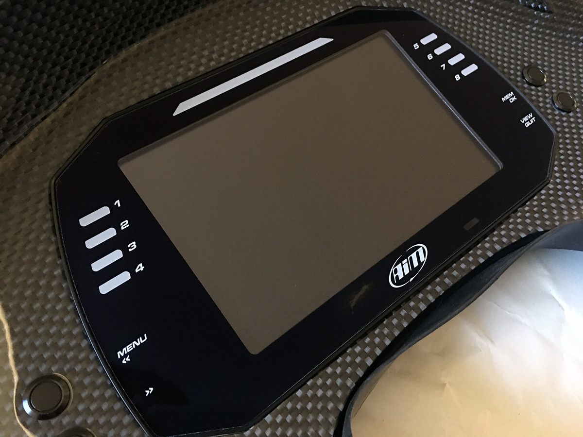
With the gauge fascia completed and in my possession, the next step was to work on the implementation of LED momentary buttons. Previously, I had non-illuminated buttons mounted on the fascia to control the menus on the MXG dash. One night when I was driving through a dimly lit street, I peered down and realized the inadequacy of having the dark buttons in the car, exaggerated by the fact that every else featured illumination. During the past Winter, while I was first getting started with this interior revamp project, I purchased a set of metal momentary buttons that matched my existing ones, except they had a red LED ring in the middle.
But before I could get into the wiring, I had to fix a small problem with the MXG itself. I accidentally put a scratch on the bottom of the screen (by the logo) when removing the fascia from the car. Trying to polish the scratch only marred it and made it worse.
Luckily, AiM has great customer support and their technical services center in Lake Elsinore was willing to replace the entire screen and bezel for me at no cost. Conveniently, AiM recently released a new bezel that is slightly sharper and I was able to acquire that upgrade in the process.

With the MXG returned and looking fresh, I mounted it back into the fascia and resumed tackling the new LED buttons.

Like before, the momentary action required a positive and a negative lead to be wired, per button. And now with the LEDs, each button had an additional pair of leads which required, in total, 16 individual 22-gauge wires to be connected. This was quite time consuming because I had to manually wind the stripped ends of each wire around the tiny poles on the buttons and then solder them into place. I used aircraft grade Tefzel wires for this job, which is overkill by an extraordinary margin. What can I say, I like excess.
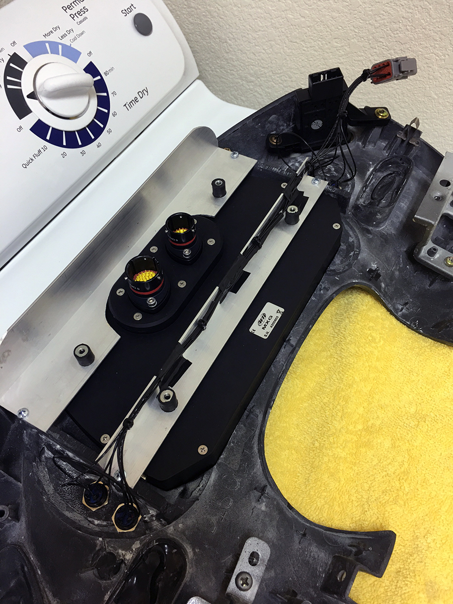
I had the Tefzel wires in the first place because of my original intent to step up the connector to an 8-block Deutsch DTM. The wires were in the same neighborhood so I bought everything at once. Previously, I used a basic Molex connector for Computers which served its purpose handily, but was lacking in terms of overall quality. Arguably, for a simple and low-stress application like the momentary buttons and their LEDs, using Deutsch connectors is like eating cereal with a 24-karat gold spoon… it is beyond reasonable comprehension but still damn cool. And I’m glad I did it because I was able to see first hand how well designed and superior the Deutsch stuff is. Yes, even plastic wire connectors can be over engineered.
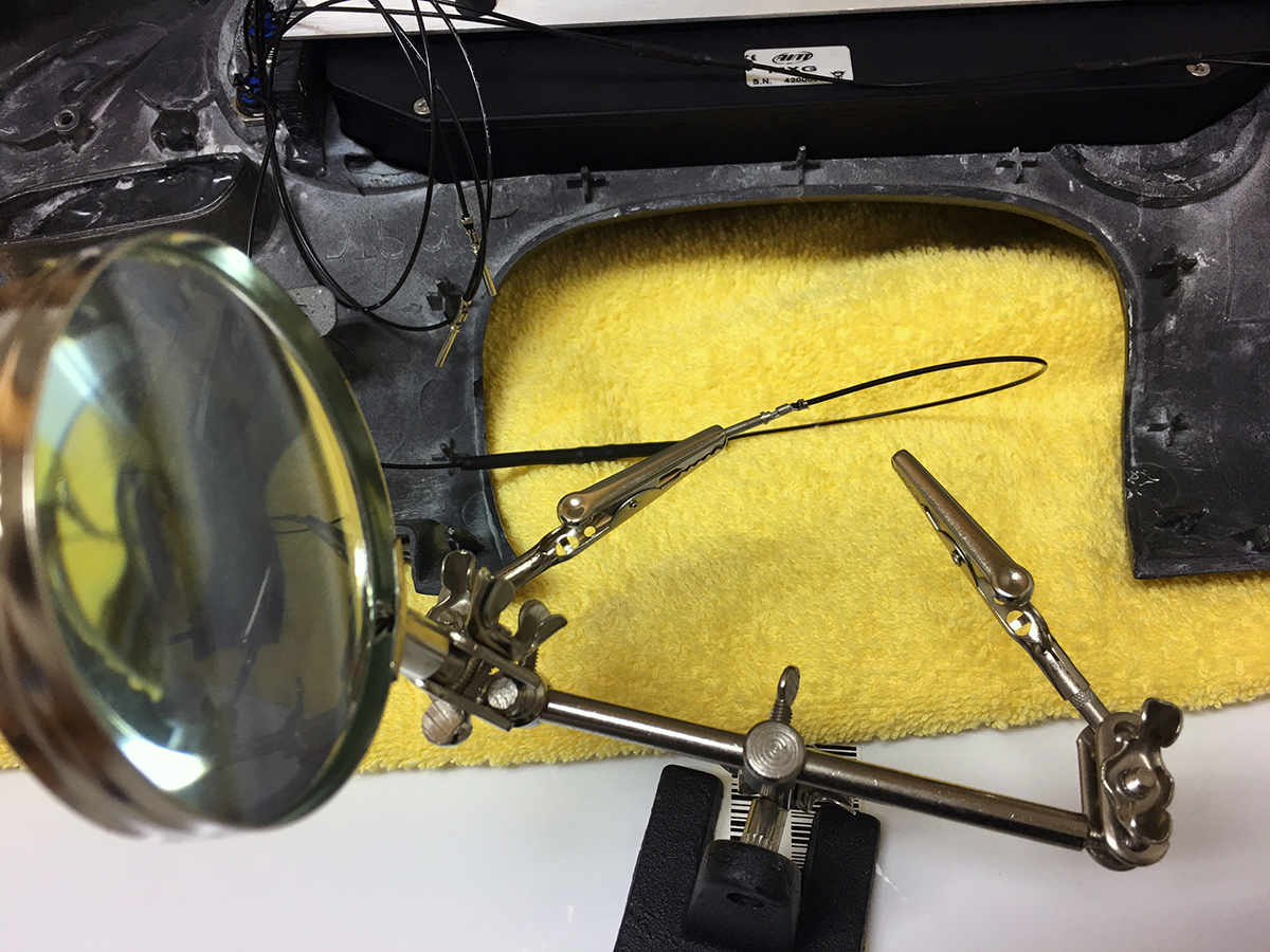
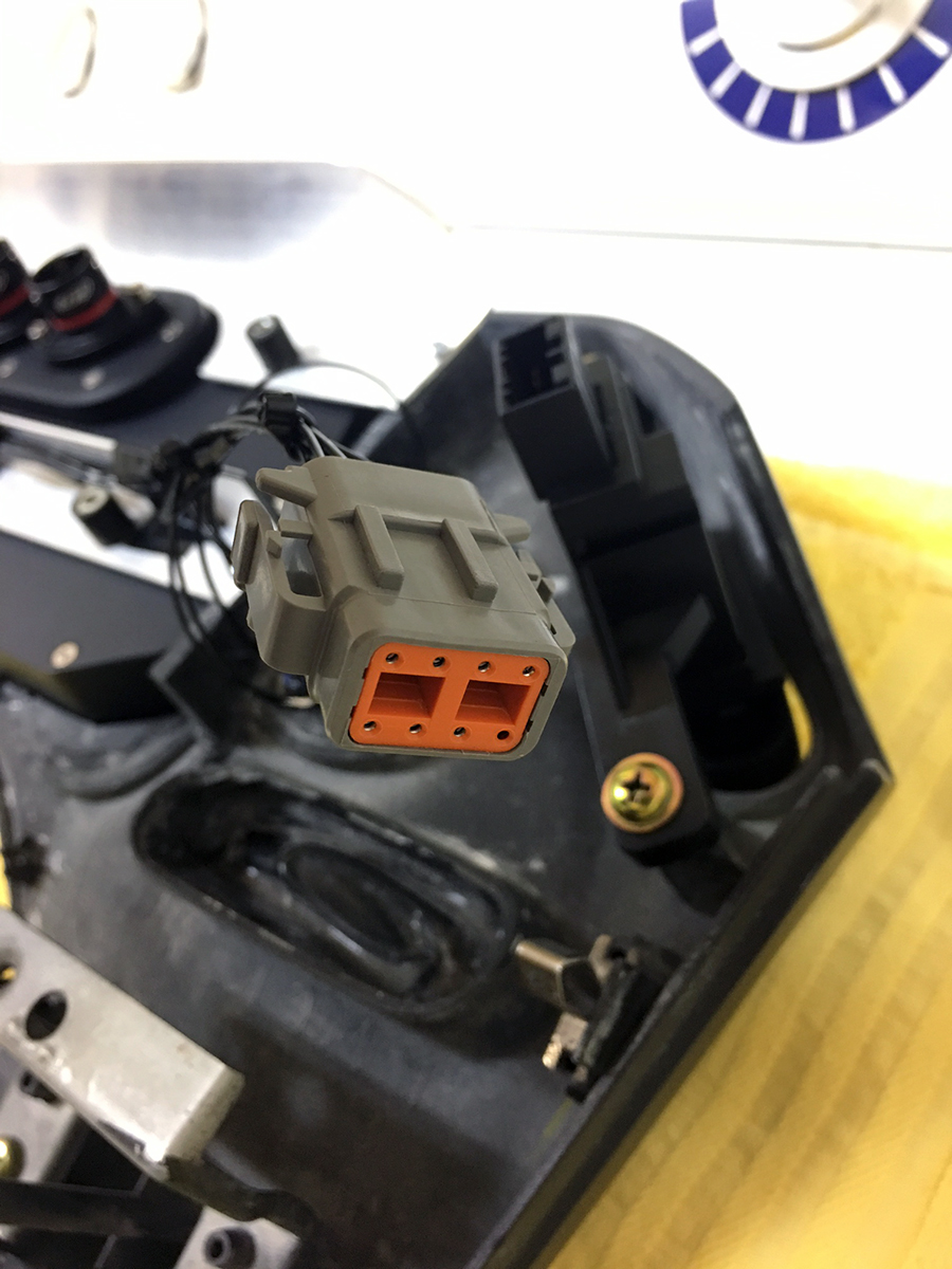
With the provided male and female crimps, everything clicked into place and assembled together inside the housings effortlessly. The pins are sequentially numbered and the housings feature rubber seals for weatherproofing (not exactly required for the interior of a car). After all of the soldering work I have been doing, I finally bought one of these Helping Hands to hold the wires in place instead of awkwardly balancing objects together all of the time.
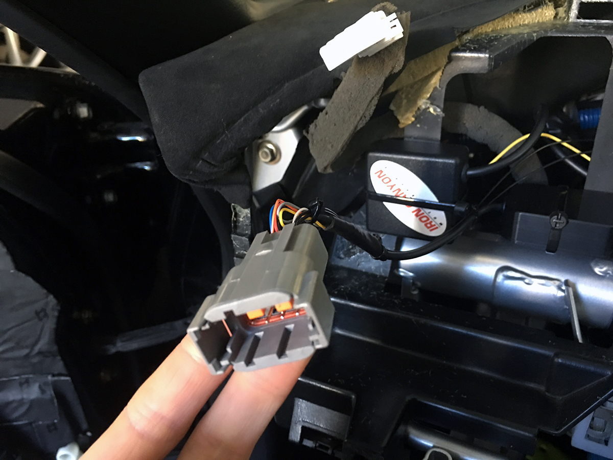
Here is a look at the connector from the car side.
And from the fascia side.
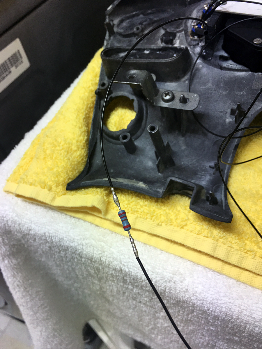
Due to the small size of the momentary buttons and consequently the LEDs inside of them, they are DC 3V instead of 12V. This meant I needed to incorporate a resistor into the circuit to convert and bring down the voltage. I wired the 4 LEDs in series and the calculated resistor needed appeared to be around 220ohm. After soldering in the resistor, I brought everything to the car and did a test run. Modern day LEDs are highly efficient, especially in comparison to conventional bulbs. This is why LEDs are far brighter under the same power circumstances. In my case, even though the car’s 12V current was being tapered down by the resistor for the 3V LEDs, I still found them to be too bright.
I cut off the 220ohm resistor and experimented via trial and error with different ohm resistors. This took place gradually over the course of a few weeks because I ended up needing to test multiple resistors.
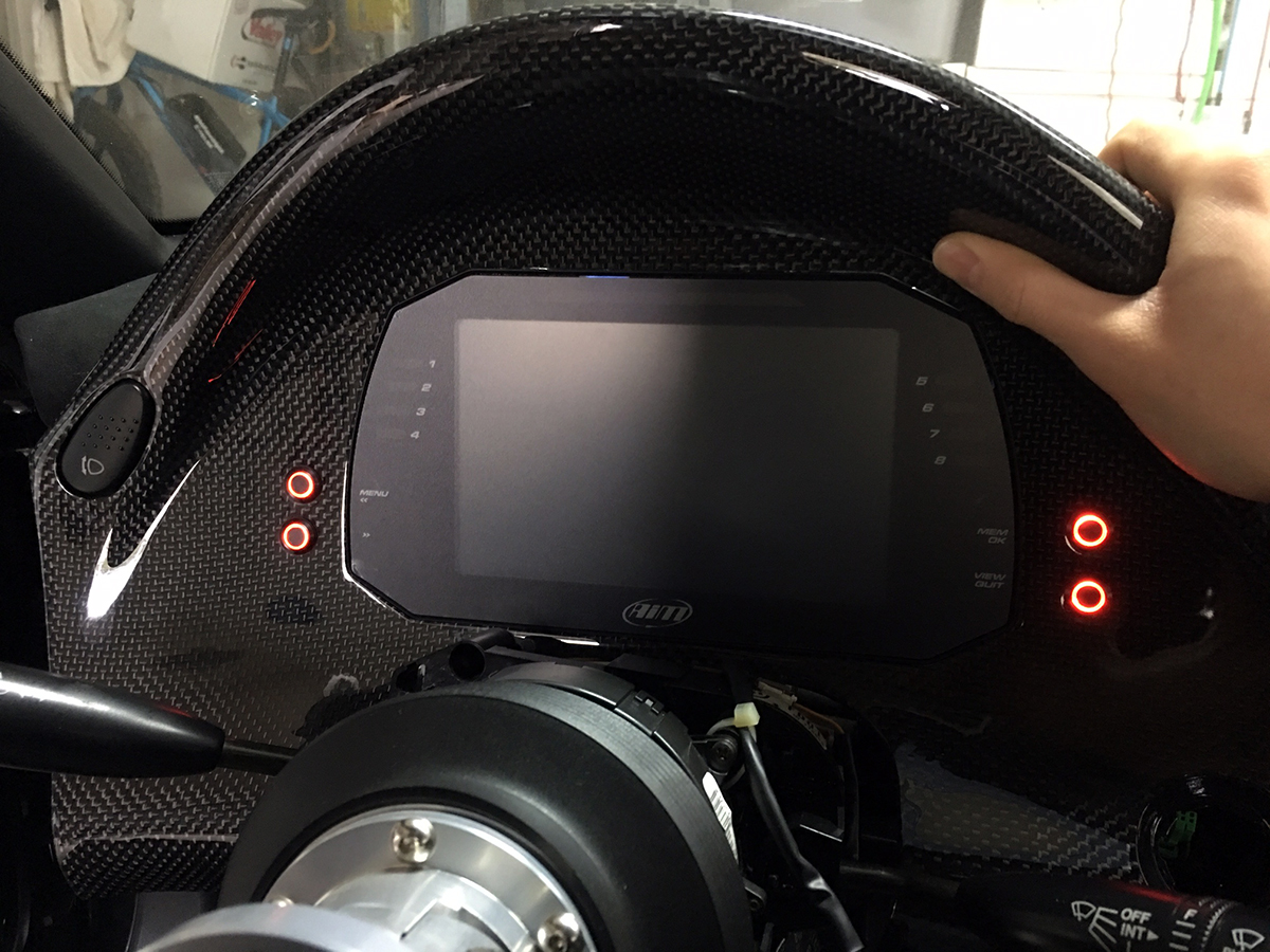
Our eyes detect brightness logarithmically so it is not necessarily straightforward to determine exactly how much the LEDs should be toned down. After many repeated trips to the local electronics store and a whole range of resistors later, I settled on 2200ohm. This placed the brightness of the LEDs about equal to the brightness of the Pioneer headunit’s illumination.
And with that, the new momentary buttons were installed and complete. Let there be light.
Just stumbled across this build.
Quick question, why didn’t you use a potentiometer to control the brightness, along with the initial resistor?
A potentiometer definitely would have been easy, I’m not really sure why. I think I just wanted to keep the overall package simple and was fixed on getting the lights to the right static brightness.