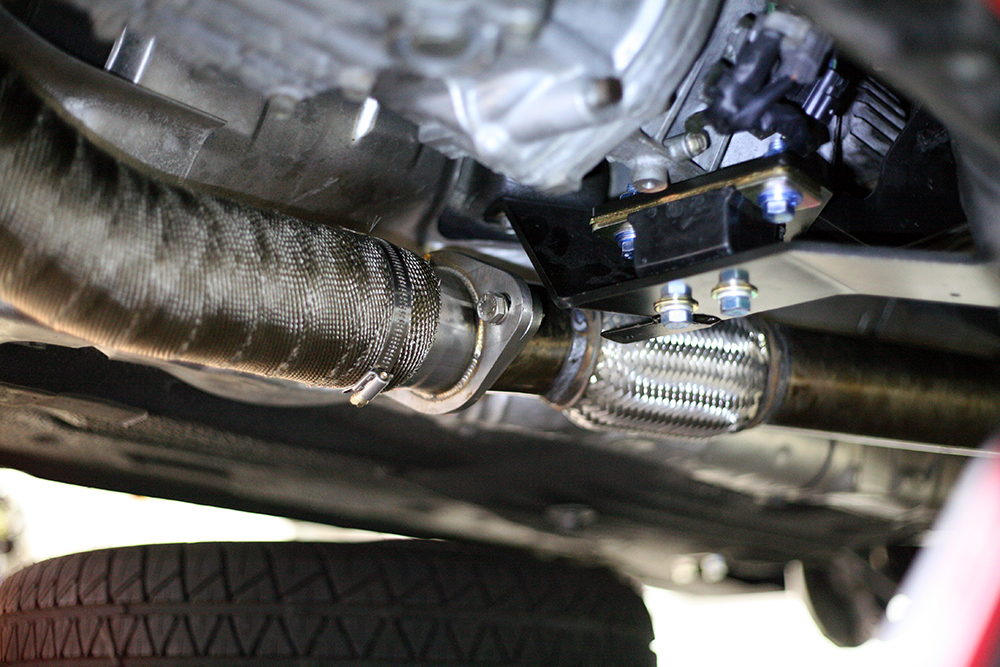
Earlier on, I brought my midpipe over to a local muffler shop to have a flex pipe welded on. I wanted this done to help relieve stress from the downpipe. This is what the exhaust system looks like hooked up.
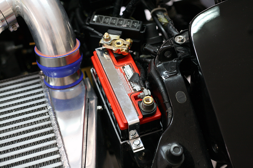
With the V-Mount in place, it occupied precious real estate at the front of the engine bay. The Braille battery I had was too big to fit. I was against having to relocate the battery inside the cabin because A.) I think a battery should stay in the engine bay, and B.) I didn’t want to extend wiring or mess with the factory configuration. I bought a Rotary Extreme mini-battery kit as the solution, and luckily, it fit perfectly with the Defined V-Mount. My anticipations of having to notch or shave material proved to be premature. Cross product compatibility is quite the convenience.
Another item I checked off the list was the fuel pump’s rewire. Even though the car has a higher-flowing Supra fuel pump, it won’t be able to perform as intended if the power delivery is insufficient. The stock wiring to the fuel pump is a guilty area of voltage drop. This is due to the redundancy incorporated into the circuit relay, which taps power from an ignition wire.
By simply bypassing this wire and connecting it to a direct source of power (the battery), it has been shown to improve the fuel pump’s voltage by 2V. Another alternative is to go all out and completely obviate the stock harness by running new wiring front to rear, with the addition of a separate relay; however, I feel that this would be overstepping what I’m trying to achieve. And more relays equal more fail points.
Thus, I opted for the former method. I cut the circuit relay’s ignition wire and redirected it to the battery with an inline 20A fuse. At the battery’s end, I cut off the insulation from a ring terminal and then crimped + soldered it on. I finished it off with marine heat shrink (this stuff has adhesive inside for extra weather-proofing) and mesh cable shielding.

My categorical imperative for this build is to avoid cutting corners – at all costs. I was immediately dissatisfied by the push-through zip ties holding on the single fan to the radiator. I knew it was going to be a matter of time for the tubes to get worn down and spring a leak, especially because all of the weight of the fan is being hoisted by them. I decided I didn’t want to drive with the fan mounted this way, not even once.
What I needed was a custom bracket to hard mount the fan. How was I supposed to get this made, and quickly? I called Defined and opened my wallet. Thankfully, they were able to cook something up for me with a short turn-around time. In order to convince a busy shop to drop what they’re doing and focus on my job, I had to offer to pay double their work rates. Expensive, yes, but there is always an opportunity cost. At least I now have the fan’s mounting figured out and off of my mind.
I first mounted the fan to the bracket with M5 stainless hardware, and then the bracket to the radiator’s bungs (which were there for the stock dual fans).
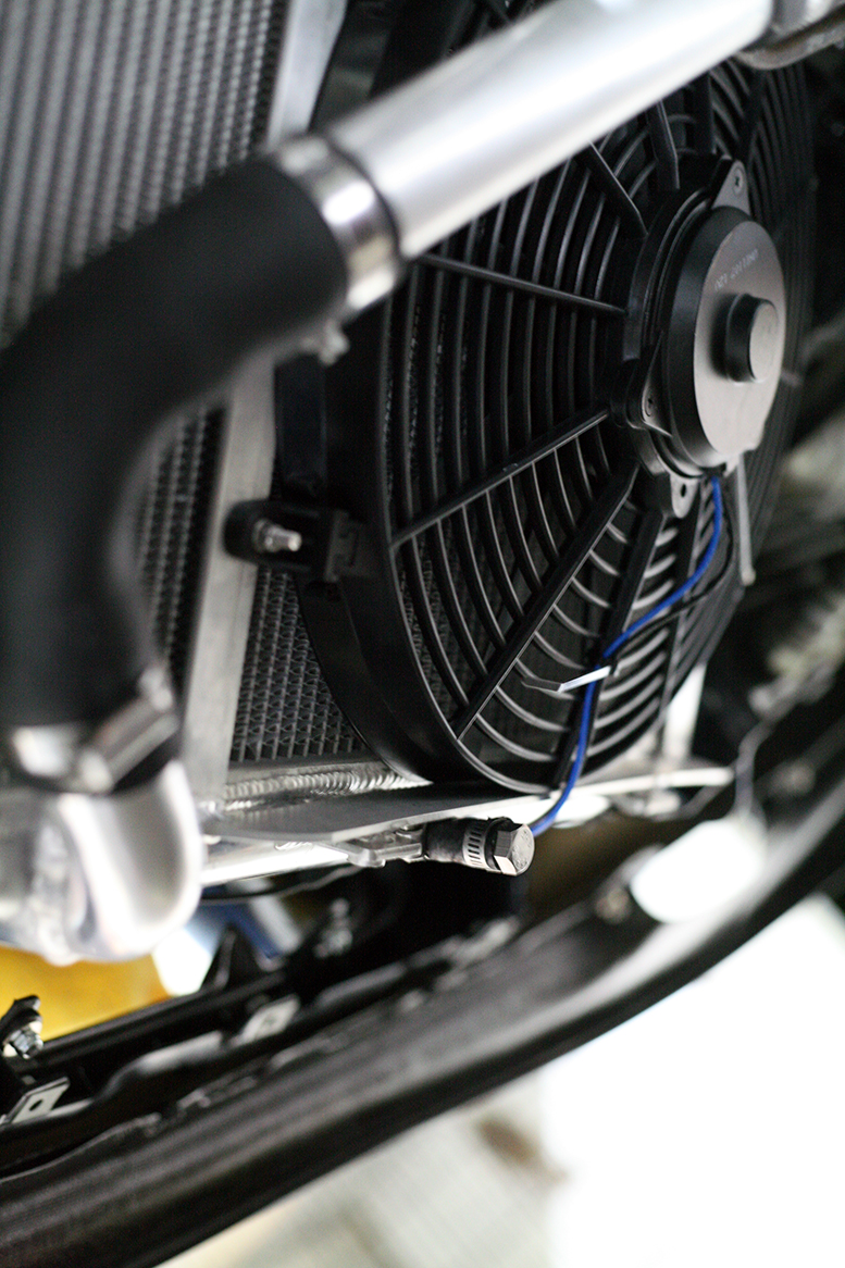
And that is indeed a Chevrolet symbol. The fan I’m using is officially licensed by GM.

Awesome progress good sir. Thank you for supporting the US with that E-Fan. lol